

This lesson tells about a special VRay modifier - VRayDisplacementMod. This modifier is used to create a “displacement” effect (blending polygons) through a texture or procedural map. Other visualizers have similar capabilities (finalRender, mental ray, brasil r / s, etc.), but the VRay blending modifier has several advantages (such as rendering speed and quality) compared to them, so with the VRay modifier get to know each other. The article highlights the main functions of VRayDisplacementMod with the help of a number of examples.
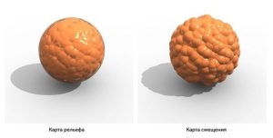
Example 1. Displacement vs Bump mapping (blending map vs. bump map).
In this example, you can clearly see the difference between applying a bump map and offset. Look at the fact that the polygonal base of the sphere does not change (that is, it remains round) when the relief map is used, but the offset already changes the shape of the sphere:
VRayDisplacementMod Modifier Parameters
Example 2. Clip mapping (removal of polygons based on the texture).
Here you can see how the modifier cuts off a certain geometry on an object. The bias card in this case is the “Noise” card, which is mixed (using the “Mix” card) with the “Gradient map” card; black areas of the mixed map will be cut off.

For this example, the explicit mapping channel option was used in the displacement map; “2D displacement” option is activated in VRayDisplacementMap.
Example 3. Landscape.
Here is an example of an offset plane. The modifier options use the 2D displacement (landscape) offset method, and the Simbiont procedural texture is the displacement map (using VRaySimbiontMtl you can use procedural shaders created in DarkTree).

Example 4. The offset on the figure.
Here the displacement modifier is applied on the figure, Cellular is used as a map (a three-dimensional map, therefore the 3D displacement method is activated).
Note that if the shape is involved in the animation, the three-dimensional map with the overlapping Object XYZ (located in the map settings under Coordinates in the Source list) will change relative to the surface of the object, because this surface itself will change its position in space. If you want to fix the map in the initial position on the moving object, then you need to add the UVW Map modifier with the Mapping to XYZ to UVW to this object, and use the Explicit mapping channel in the map for the Source list.

Example 5. The option “keep continuity” (keeping sharp corners of an object when it is displaced).
The “Keep continuity” option is very useful for objects that have split normals (see the middle picture) on the adjacent polygons. This is usually due to differences in the smoothing groups of the polygons (that is, in smoothing groups). On the middle image you can see what happens. Activating the “Keep continuity” option will help solve this problem. Also, this option will help smooth the edges between different material IDs (this happens when the Multi / Sub-Object material is used).

Example 6. The “Subdivision” offset method.
This example shows the “Subdivision” offset method. This method is somewhat similar to 3D mapping, but differs in that an anti-aliasing is also applied to the object, similar in effect to the result from the MeshSmooth modifier.

Example 7. Parameter «Split method» (method of separation of polygons at their offset).
This example shows the effect of using the “Split method” parameter. To better illustrate the example, a standard material with the “Faceted” option enabled was assigned to the sphere, the “VRayEdgesTex” map is located in the “Diffuse” slot to display the edges of the polygons on the object. Note that the use of the “Binary” setting leads to a change in the orientation of polygons that are shifted by the modifier. But if you use the “Quad” setting, the orientation change in space does not occur.

Example 8. Vector offset.
This example will demonstrate in detail the effect of applying vector offset. The first image on the left shows an object with a complex geometry, which is then converted into an displacement map (this requires a simpler object to which the material “VRayVectorDisplBake” should be assigned). And already in the second image, a ready displacement map is presented (red, green, and blue colors indicate displacement vectors in the space “UVW”). The last image shows the application of the vector offset map to another object using the “VRayDisplacementMod” modifier.

An object with a complex geometry, as well as its simplified version with the material “VRayVectorDisplBake”.

Here is the displacement map obtained using the Render to Texture function. VRayCompleteMap was used to get the map. The finished map was saved in the EXR format. 
The displacement map is applied to another object using the “VRayDisplacementMod” modifier, in which the “Vector displacement” option is enabled.
Example 9. Border texture.
This example shows a plane whose offset map has a negative value. With the default for texture boundaries, we will not be able to see the offset geometry in the opposite direction. But if we change the texture boundaries to -1 and 1, then the displacement of the geometry will occur both up and down. 


